I like input devices. One of my favorites are mechanical keyboards. In the last two years or so I have been following the rather active mk subreddit and dug my nose into this topic.
After some purchases and trying out several keyboards I decided I wanted to try my hand on handwiring – here a build blog for anyone who is interested in this topic.
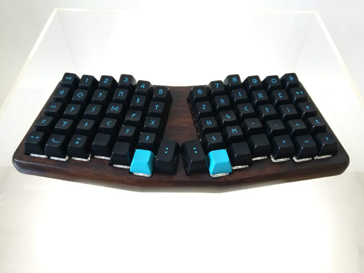
The Atreus62 is a bigger version of the original 42 ortholinear keyboard by Technomancy. Profet23 took the original design and added another column and another row on each side. While the 40 key keyboards are incredibly cute it definitely needs quite some time to get used to them. The bigger drawback for me was not learning the layers but rather forgetting it when not using if for a while.
Bamboo Case by FalbaTech
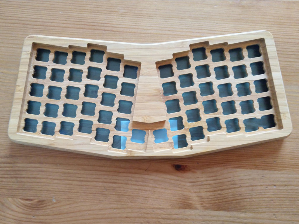
The case options for the atreus62 are unluckily rather limited. You can either go with the original sandwich cases from profet23 or go with a few alternatives. I decided on a bamboo lift case from falbatech for a couple of reasons. First of all its the only non-floaty case I found (this means the switches are deeper down and you don’t see them from the side), second they are from poland (i am from austria) so shipping is cheaper and last but not least its the nicest design that I found. Shipping took around two weeks. Initial impression was somehow meh, the finish was rather rough and some edges a little bit jaggy, also one of the dividers between the switches was broken out.
Staining
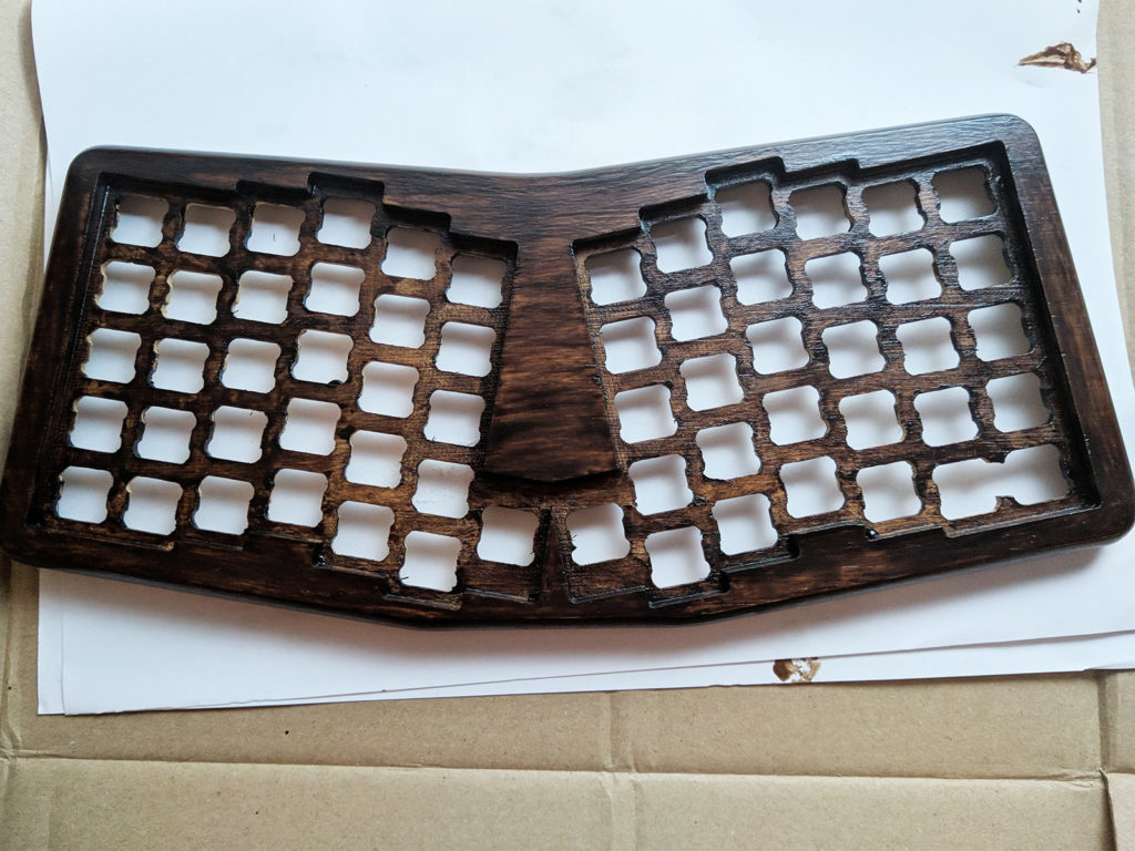
I did not want to keep the light bamboo look so my first task was to stain the wood – i wanted something like a dark oak look. Got some woodstain from the local hardwarestore and made two rounds of staining.
Adding Switches
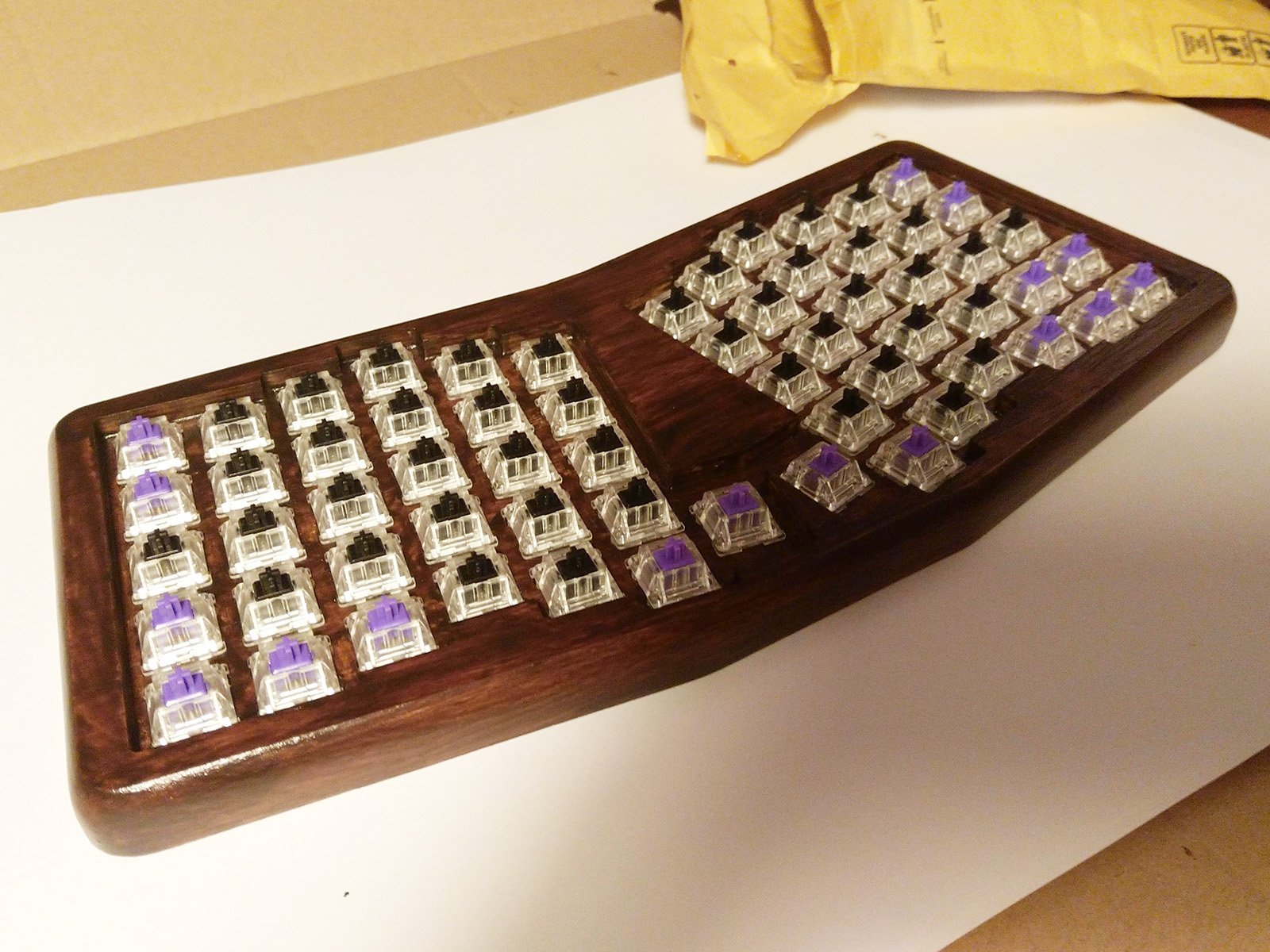
Fitting in the switches. I went for a mix of zealios 62g for the modifiers and retooled mx blacks in zealios housings for the alphanumerics. I wanted to try linear switches for a while already. The switches were bought at reddits mechmarket.
Hotglue
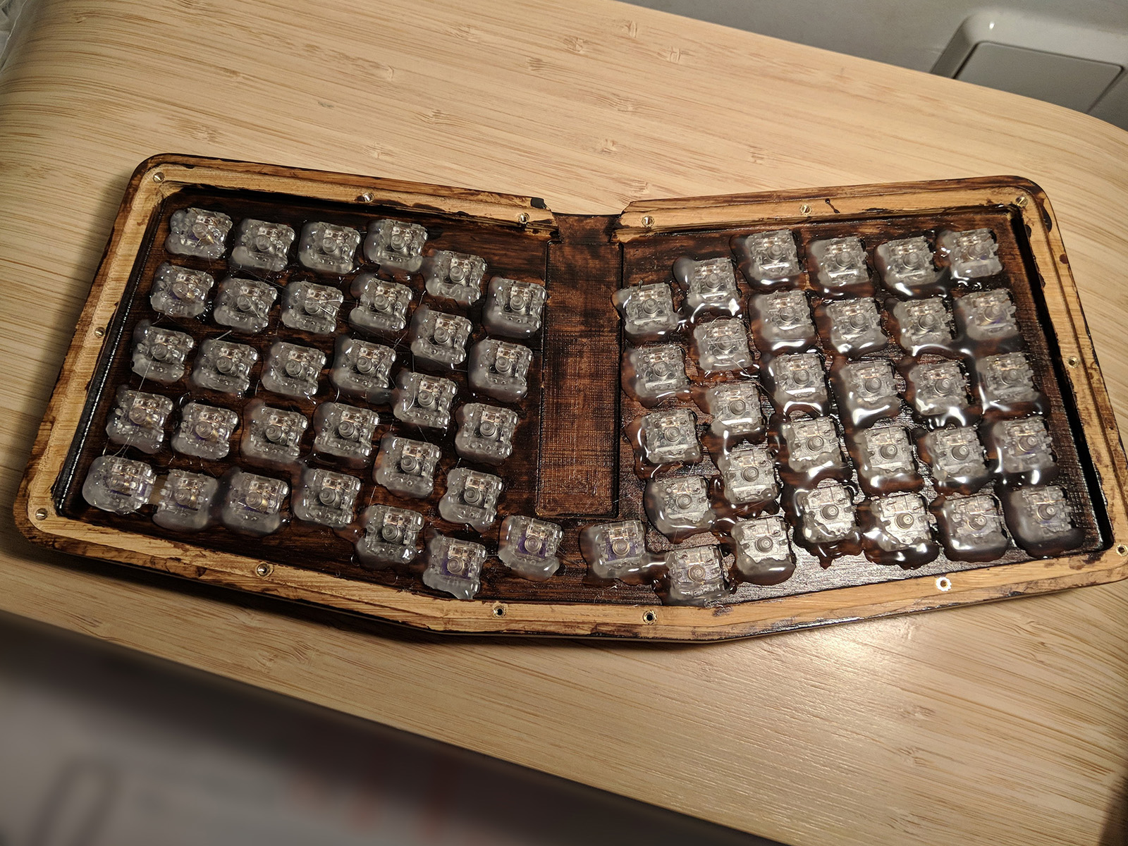
I originally thought that if the switches sit tightly enough I will skip glueing them into place. After a couple of tests with my keysets I noticed that its way to loose – better to glue them in then to risk ripping out the switch when changing keycaps. Well, another trip to the hardware store for the glue gun.
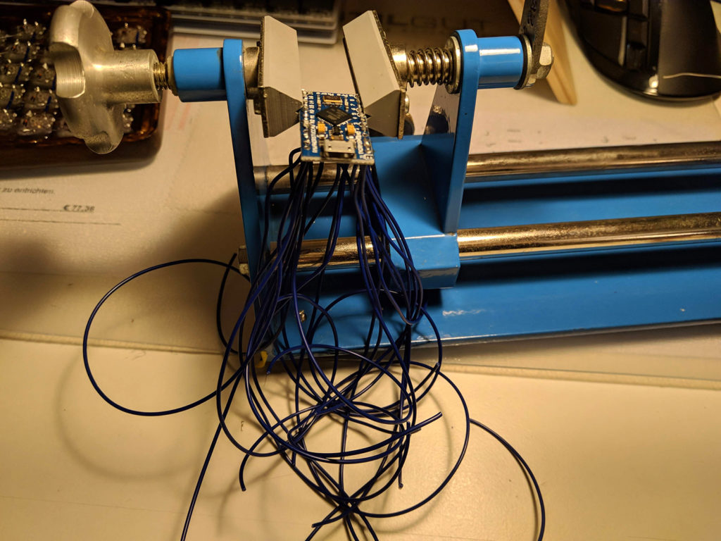
Soldering Columns
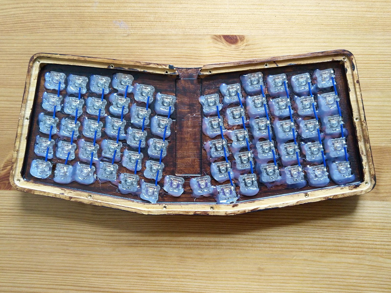
Now it got interesting – and timeconsuming. I checked a couple of other build logs and then decided to do it pretty standard. If I would do it again I probably would start with the rows, not the colums. I was a bit afraid of the soldering part. I do know how to solder but I was afraid that with thin wire I would burn the isulation rather easily. Luckily it worked rather well. I used a cheap soldering iron with a pointy tip, so the heat would just be on a small area. For the wire I tried three different ones, this one is actually a rather thin flexible wire with a rather thick insulation. Stripping the wire takes some practice to get the right length but after a while you get used how wide it needs to be. I used a stanley knife since I did not have a wire stripper. It works, just takes a while.
Soldering Rows
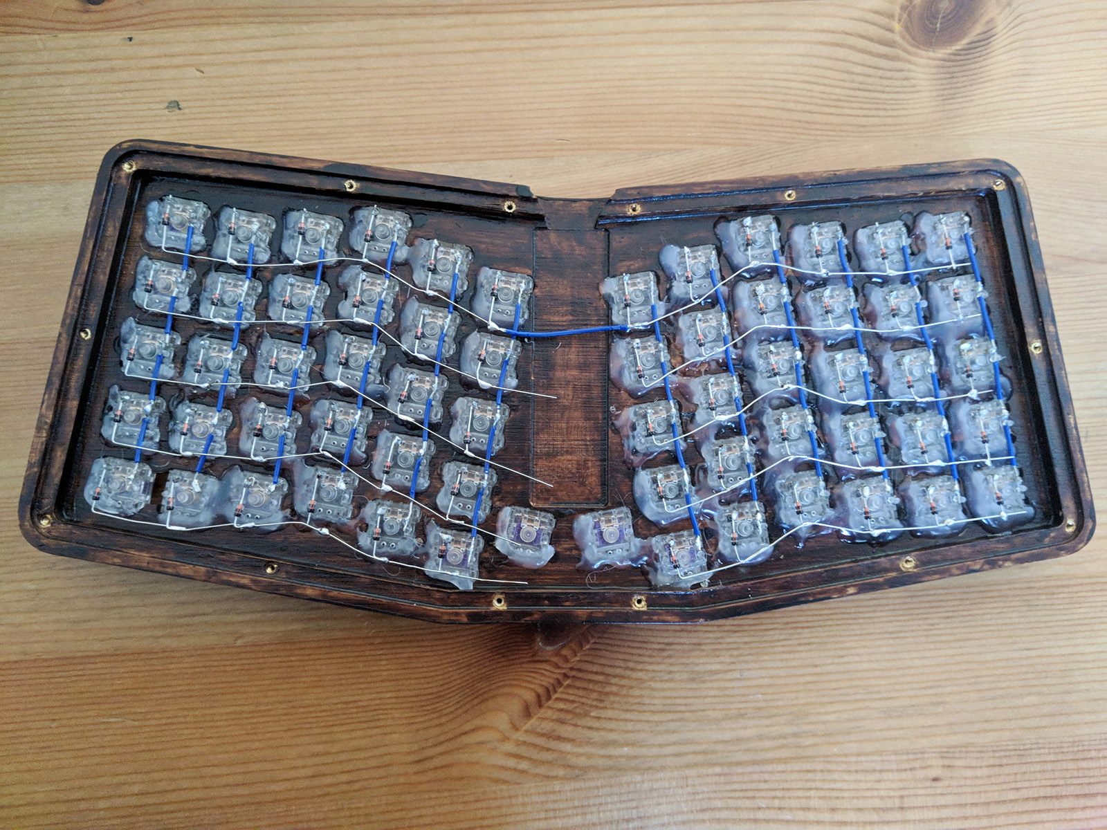
The next thing that I was worried about was soldering the diodest. One thing that helped me a lot is one of those third hand soldering aid – without it it probably would have been a lot more complicated. While the work was easier then expected it also took quite a lot more time then I thought.
Pro Micro
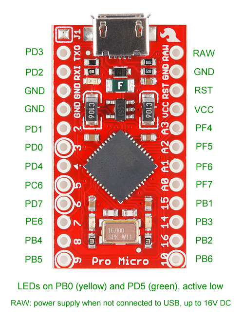
Now that we finished the matrix it is time to hook up the microprocessor which will figure out which key got pressed. It took me a while to unterstand what actually happens there – although its not as complicated as it may seem. The processor has to get an input from each colum and each row. When a key is pressed the promicro can easily figure out which output it has to produce.
So far, so good. Now we just need to know which pins we can use on the pro micro. This took me a while to figure out, but I found a nice diagram over at deskthority. Since I am lazy (or lets say not very good in programming) I thought it would be the easiest to use the original firmware from profets atreus board. The pins that are used are defined in the config.h repository on github.
// wiring of each half
#define MATRIX_ROW_PINS { D2, D3, D1, D0, D4 }
#define MATRIX_COL_PINS { F4, F5, F6, F7, B1, B3, B2, B6, B5, B4, E6, D7, C6 }
Soldering the Pro Micro
Apart from the 18 wires for the colums and rows I soldered another two wires to reset the pro micro – we need that later to flash the firmware. The pro micro resets if you connect the RST and the GND two times in a row.
Wiring the Pro Micro
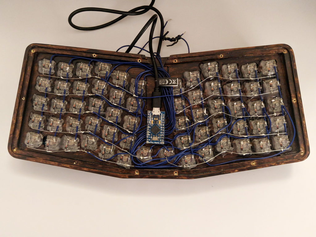
Finished connecting the Pro Micro. I also already flashed the processor with the atreus62 default firmware, so pretty sure it will work. Spoiler: it did not. Only thing that worked was that the led of the Pro Micro lighted up, but no keypresses register. At 2 am I finally give up, still wondering what went wrong.
Next day I start troubleshooting and I notice that the Pro Micro is sending the correct signals if you connect a column and a row direclty at the board. This means the mistake must be somewhere between the switches and the controller. If only a part of the keyboard would work it would mean that its probably the soldering, but since nothing is working the only thing left are the diodes. While I soldered the diodes correctly according to all the diy guides that I checked I thought that must be it. So much for using the default firmware. Back to QMK central, install some packages, set up the environment, edit the config.h and change the diode direction from ROW2COL to COL2ROW. compile the firmware, flash it with QMK toolkit and what do you know – everything works!
So moral of the story, if you use the default atreus62 firmware check those settings in case if you have any issues. The other problem that I ran into was that my keyboard was mirrored – while the rows were correct from top to bottom (D2, D3, D1, D0, D4) the colums need to be the other way around. F4, F5, F6, F7, B1, B3, B2, B6, B5, B4, E6, D7, C6 are the colums from right to left, not the other way around. Since I had to do my own compiling of the firmware it did not matter since I could change it in the config.h.
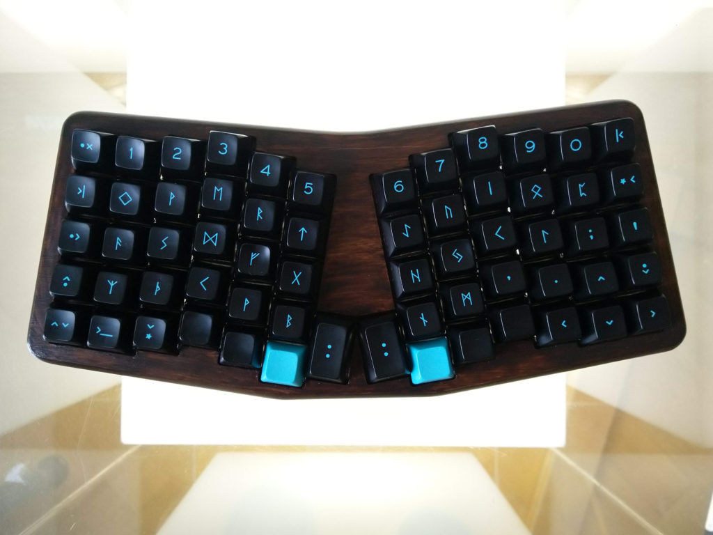
Finished Front
Finished Back
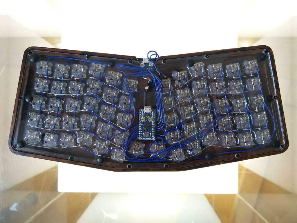
Thats pretty much it – Last but not least I added an usb output socket so I could connect normal usb micro cables. While doing that I managed to give the case a hairline crack because apparently bamboo wood is quite sturdy and not very flexible. Well, this gives me a good excuse to even out the staining.
Another thing that is still unsolved is the reset button – I planned to add a microswitch for the reset, but all the switches I tried so far were too big.
Anyway, all in all I am happy how the whole project came together, it was an interesting experience and I did learn a couple of things.